Algorithmic Gauntlet
In broad strokes, the main points of this project are different sorting and searching
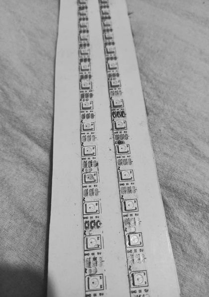
algorithms visualization,RGB led strip as an array and respective pointers to the
array index, 3D gauntlet as a control for program flow, web application , and
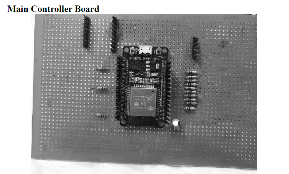
particularly ESP32 as a microcontroller Arduino.
There are two principal applications of algorithm visualization: research
and education. Potential benefits for researchers are based on expectations
that algo-rithm visualization may help uncover some unknown features of
algorithms.
This can help to examine the working of different algorithms.
This can help one to estimate counts of steps to execute an algorithm over
the data structure
Each button connector cable has two wires, one for VCC and one for ground. One
end has spade connectors that fit the leads on the back of the button -- attach the
ground to the "normally open" lead, and VCC to the "common" lead. In this
configuration, when the user pushes the button, the circuit is completed and the
microcontroller will read HIGH on the corresponding input pin.
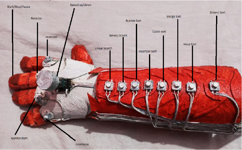
#define NUM_BUTTONS 13
Button gButtons[NUM_BUTTONS] = {
{ 26, GenRandom, false },
{ 25, GenNoise, false },
{ 35, Reverse, false },
{ 12, LinearSearch, false },
{ 14, BinarySearch, false },
{ 27, Reserved, false },
{ 23, BubbleSort, false },
{ 5, InsertionSort, false },
{ 13, QuickSort, false },
{ 33, MergeSort, false },
{ 32, HeapSort, false },
{ 15, BitonicSort, false },
{ 34, StartPause, false },
};
The other end of the cable has a JST connector (the little white thing). They only go
into the receptacle in one way, so there is no way to accidentally reverse VCC and
ground.
What I did is build a little harness for these connectors. I solder a series of JST
receptacles onto a piece of protoboard and then run wires back to Dupont connectors
that I'll plug into the microcontroller. The red wire is the VCC line, and it connects to
all of the JST receptacles. The blue wires are the ones that are separate for each
button.
The rotary encoder lets the user control the speed of the algorithm. I use a module
that comes as a breakout board that includes pull-up resistors for the two data lines
(yellow wires). This one also happens to be a button, but I'm not using that feature.
The other two wires are VCC and ground.
Rotary encoder, as opposed to a potentiometer, is that it just signals rotation
(clockwise vs counter-clockwise) to the microcontroller, so it's easy to change how
the value is interpreted. For example, one can give it a sense of acceleration (like a
mouse) when the user is spinning it fast.
#define NUM_BUTTONS 13
Button gButtons[NUM_BUTTONS] = {
{ 26, GenRandom, false },
{ 25, GenNoise, false },
{ 35, Reverse, false },
{ 12, LinearSearch, false },
{ 14, BinarySearch, false },
{ 27, Reserved, false },
{ 23, BubbleSort, false },
{ 5, InsertionSort, false },
{ 13, QuickSort, false },
{ 33, MergeSort, false },
{ 32, HeapSort, false },
{ 15, BitonicSort, false },
{ 34, StartPause, false },
};
Technologies:
- - C++
- - HTML, CSS, JavaScript
- - Arduino
- - FastLed Library
Laboratory Admin Dashboard
Sample ID Form